
Case study · MPM analysis
Reading a long-runout landslide with the Material Point Method
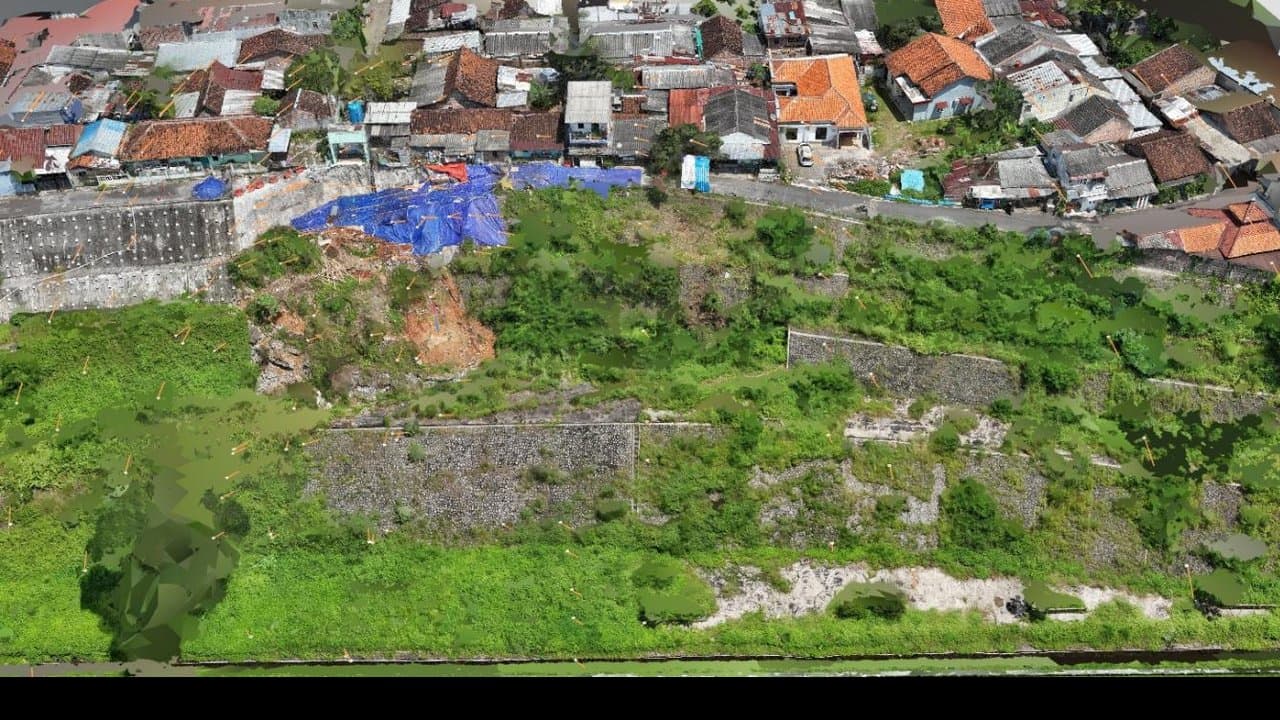
The cut slope at KM 430C failed progressively. It started at the uppermost berm and within a few weeks spread over the entire slope, travelling a long way downslope. Conventional methods could not explain this behaviour, so GFM modelled it with the Material Point Method.
- Location
- Semarang Toll Road, KM 430C
- Client
- PT Jasamarga Tollroad Maintenance
- Year
- 2025
- GFM's role
- Analysis and design
The problem
The failure started at the top and dragged the slope below with it
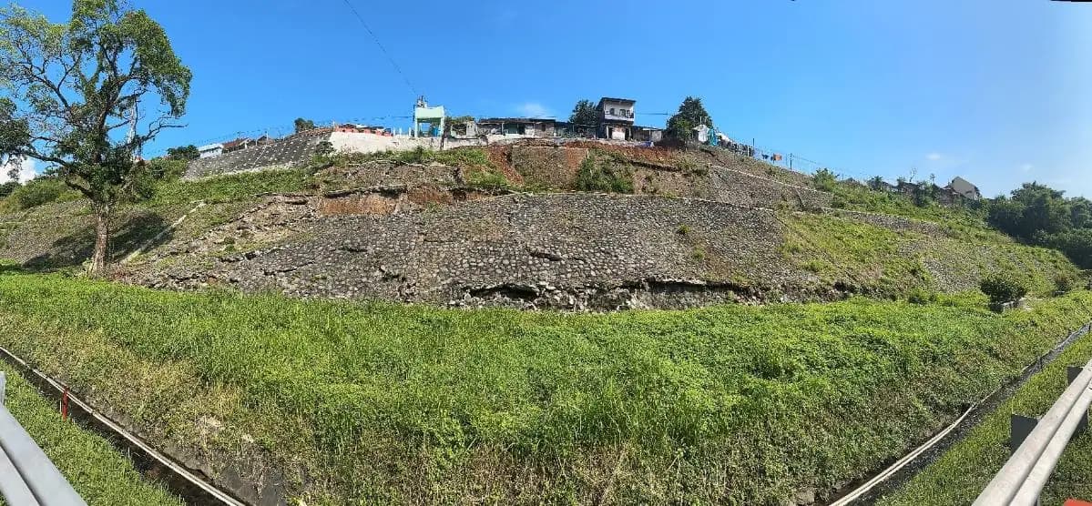
The ground investigation found very soft to soft clay in the upper slope, with the slip surface estimated at 8–15 m depth. The existing horizontal drains no longer intercepted the groundwater table, and water was seeping out erratically across the slope face.
On site, failure began at the uppermost berm, then dragged the lower slope along and kept moving after the first slide. A conventional stability analysis gives a single factor of safety without explaining this sequence. A design that misreads the mechanism risks strengthening the wrong part of the slope.
Why MPM
For a landslide that travels far, the question is not only “is it safe?”
MPM represents the soil as thousands of material points that move freely through a computational grid. Because it is not bound to a mesh, the method remains stable under very large deformations. The whole failure process can be followed: when shear bands form, where they propagate, how far the soil travels, and where the material comes to rest.
Conventional stability analysis
How safe the slope is: a single factor of safety on one slip surface.
Does not explain the failure sequence, how the landslide propagates, or how far the soil travels.
Material Point Method (MPM)
The failure sequence, progressively forming shear bands, runout distance, and where the material comes to rest.
Requires good soil parameters and longer computation time.
Simulation results
Two shear bands, one propagating landslide
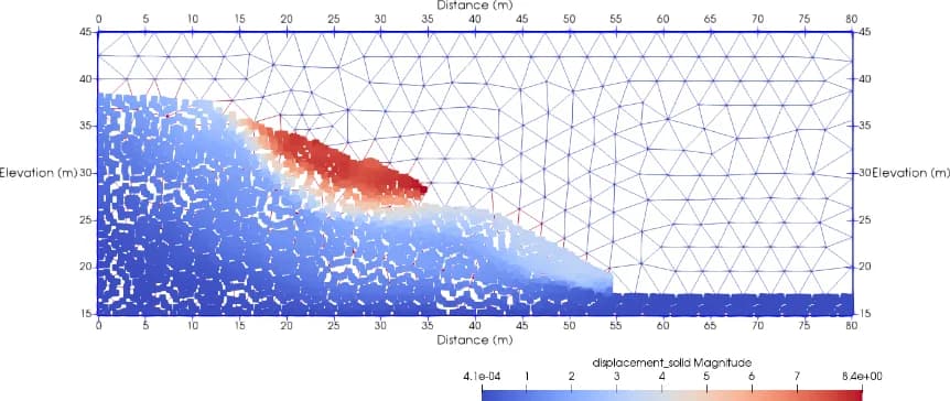
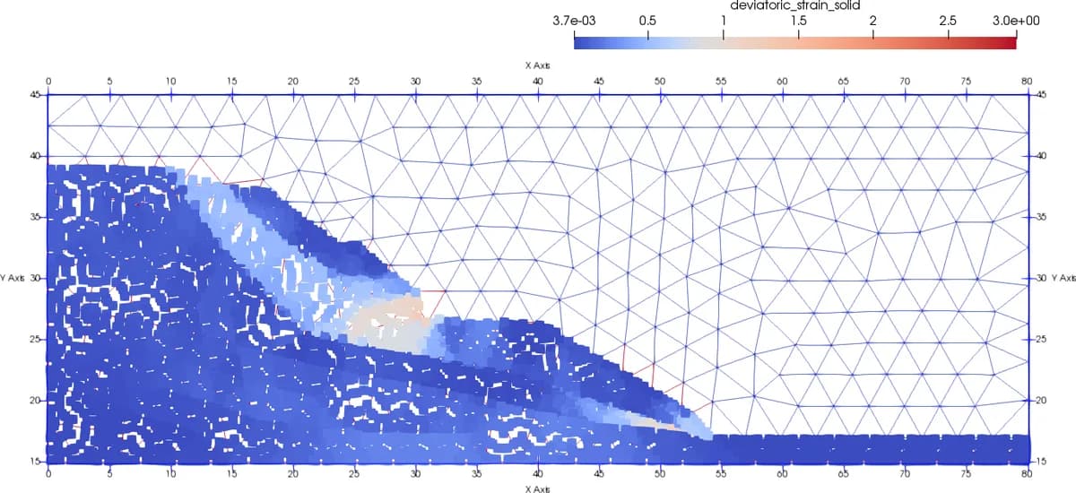
The simulation shows progressive failure: the upper slope fails first and forms the first shear band. Its thrust then triggers a second shear band in the lower slope. This matches what happened on site, including the continued movement after the first slide.
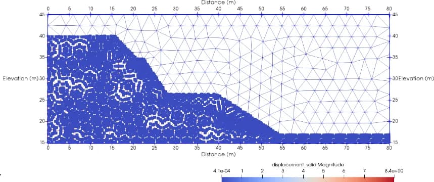
Initial state
Geometry of the cut slope before movement.
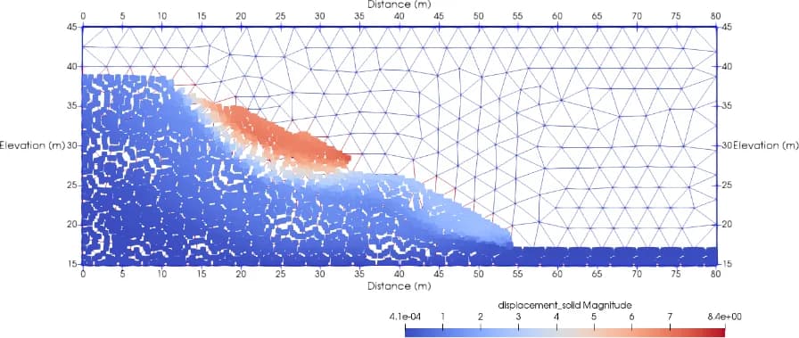
Upper slope fails
The soil mass of the upper slope starts to slide.
End of simulation
Material pushed far downslope: runout of the upper slope exceeds 15 m.
What it means for the design
- Water is the trigger. Without working drainage, any strengthening works against a saturated soil mass.
- The upper slope pushes the lower slope. Strengthening only at the toe does not stop a mechanism that starts at the top.
- Structures at the crest must bear below the slip surface, not on ground that moves with it.
Remediation concept
A box structure on minipiles, combined with subdrains
Alternative considered
Embankment rebuild + bored-pile wall
- The bored piles would have to resist the thrust of the entire soil mass moving above a deep slip surface, so their lateral deflection would far exceed the allowable limit.
- Pile bending moments are very large, so the diameter and reinforcement required are out of proportion to the safety gained.
- Rebuilding the embankment adds load at the crest, exactly where the failure starts.
- It does not address the groundwater that triggers the failure.
Selected concept
Box + minipiles + subdrains & blanket drain
- A light concrete box replaces the embankment, reducing the load at the crest.
- The minipiles are not used to retain the landslide. They carry the road load down to firm strata below the slip surface.
- Subdrains and a blanket drain lower pore-water pressure, acting directly on the trigger.
- Regrading and a counterweight berm reduce the driving force and add resistance at the toe.
- Meets the Pd T-09-2005-B factor-of-safety criteria for both normal and worst-case groundwater levels.
- 1
Concrete box at the crest
The road is rebuilt on a light, stiff box structure, reducing the load on the slope.
- 2
Minipiles through the slip surface
The box load is carried down to firm strata below the sliding zone, not into moving ground.
- 3
Horizontal subdrains
Two rows of perforated pipes lower the groundwater table within the slope, the main trigger of the failure.
- 4
Slope regrading
The slope is flattened to reduce the driving force from the soil mass above.
- 5
Filtered blanket drain
A gravel and filter layer on the lower slope discharges seepage without washing out fines.
- 6
Counterweight berm at the toe
Spoil from regrading is reused as a stabilising berm at the toe.
Construction sequence
The work sequence is part of the design
Because the slope was still moving, the construction sequence is fixed on the design drawings so that the works do not trigger a new failure.
- Step 1
Drainage first
Horizontal subdrains and the blanket drain are installed first, so pore-water pressure drops and the slope begins to stabilise.
- Step 2
Regrading & counterweight
The slope is flattened; spoil is placed back as a counterweight berm at the toe once the drains are working.
- Step 3
Confirm no movement
Piling starts only after continuous (7×24 h) field monitoring confirms the ground has stopped moving.
- Step 4
Minipiles & box
Minipiles are driven through the slip surface, then the concrete box is built as the roadway at the crest.
Is your slope moving further than expected?
We can model the failure mechanism and runout with MPM, then design a remediation that targets the cause.
Or write directly to contact@gfm-consult.com